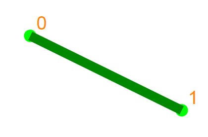
Create a new node. Left click on the page somewhere to the left of the vertical bar (nothing will stop you from clicking on the right but you'll end up with selection data overlaying your graphic). You will see an orange number next to the node. This is its ID number.

Create another new node. Left click again in a new location. You get another new node and an edge appearing between them. Edges will be drawn in thick green lines until the polygon is closed. After closing, edges will have ID numbers next to their arrows.
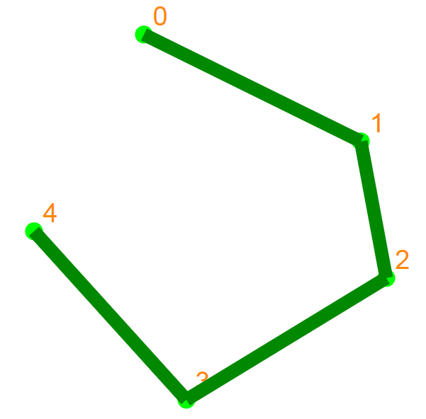
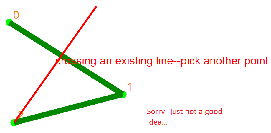
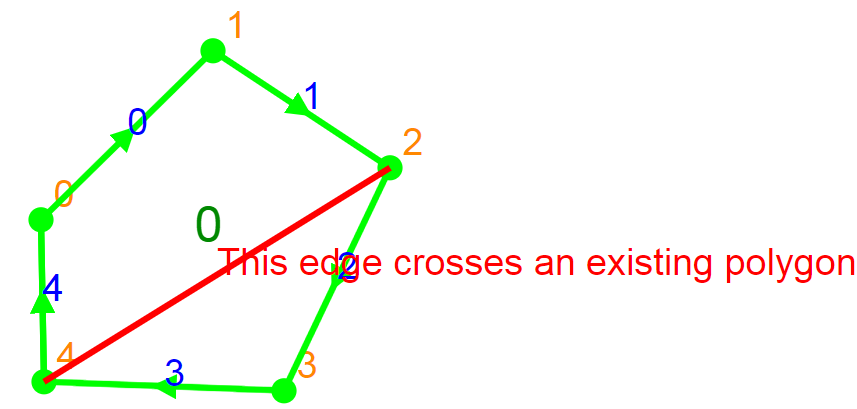
Keep creating new nodes. Create as many new nodes as you like in this manner. No edge crossings are allowed--you'll be told to select another point elsewhere.
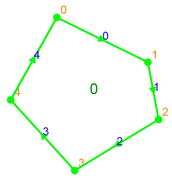
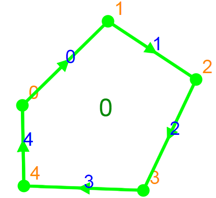
Close your polygon by clicking on the first node you created (in this example, node 0). The thick lines will turn to thin lines with embedded arrows and ID numbers. The arrows indicate their direction with respect to your digitizing pattern. For a given edge, the arrow points away from the start node and toward the end node. The polygon's ID number appears at its centroid.
Create more polygons. You can start a new polygon by clicking in empty space or by clicking on an existing node. You can trace multiple existing edges by clicking on consecutive existing nodes:
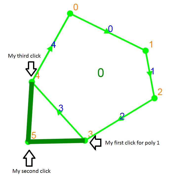
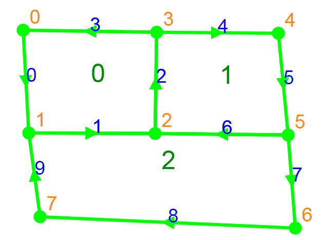
And then close the polygon by returning to the first node (in this example, node 3). Notice that the existing node and edge IDs do not change; they are now shared by poygon 0 and polygon 1. Given the original digitized direction of edge 3, polygon 0 is on the right and polygon 1 is on the left.
A couple things to remember:
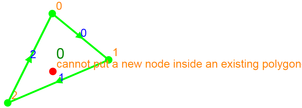
The app won't let you create a new node inside an existing polygon. That would be cool if it were capable of subdividing existing polygons but it's not--as a world leading GIS manufacturer would say, that's fixed in the next version. For now the app just tells you to pick another point.
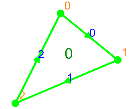
If polygon 0 has already been digitized:
Creating a new node inside it generates an error:
And it won't let you connect 2 non-adjacent nodes in the same polygon. That would lead to the same issue. Desirable, but didn't make the cut for this version.
So, if polygon 0 is an existing polygon:
Then trying to separate it into 2 polygons with a new edge is illegal (for now...):
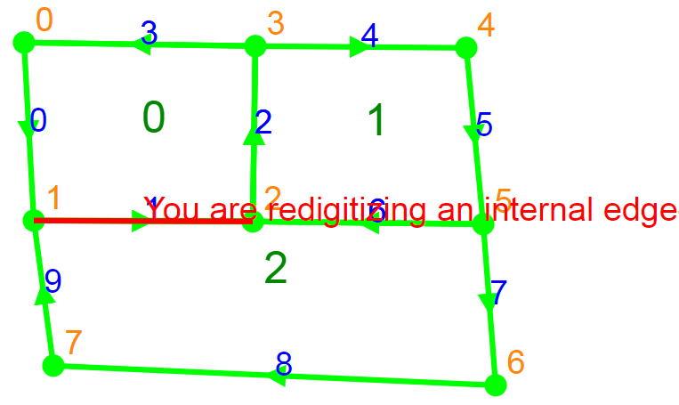
The app also won't let you digitize internal edges. I define an internal edge as one that does not have WORLD (the area outside of all digitized polygons) as a neighbor. Redigitizing these edges would create some ambiguous relationships that would require the app to figure out what the user wanted. For the same reason, the app will warn you about starting a new polygon when you click on any node that is only connected to internal edges. (to be fixed in version 29 with a masterful AI solution).
Suppose you've created this set of polygons:
Trying to use edge 1 to create a new polygon doesn't work. It already has polygon 2 assigned to the right side and polygon 0 assigned to the left:
Selection Instructions
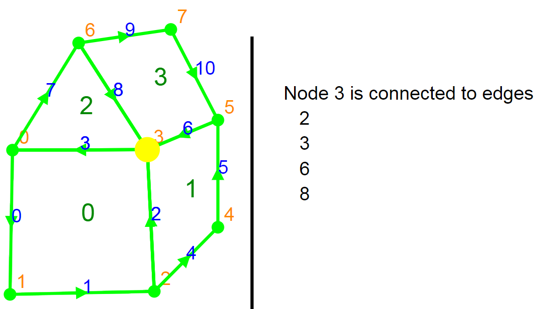
Hold down the shift key while clicking. If you click near a node, an edge, or within a polygon, the feature is selected with a highlight color and connectivity information appears to the right of the vertical bar. Selection is prioritized by node, then edge, then polygon. Try it out and you'll see what I mean.
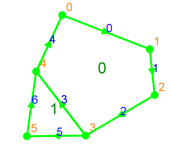
When you select node 3 in this image, you're told that node 3 is shared by edges 2, 3, 6, and 8.
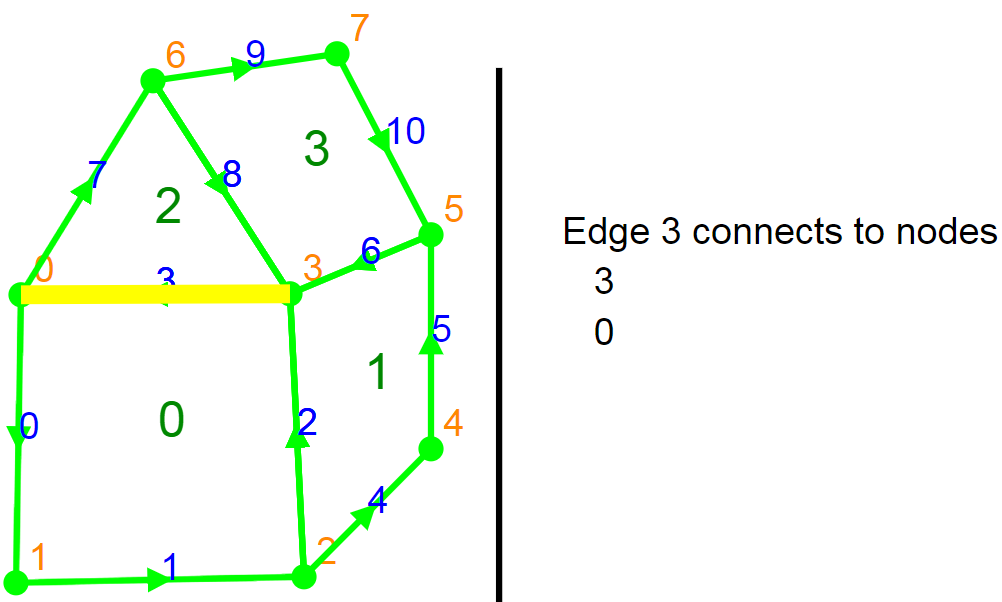
Selecting edge 3 provides its starting and ending nodes. I have recently updated this feature to show adjacent polygons on each side (left and right) of the edge, given its original digitizing direction (shown by arrows on selected edges)
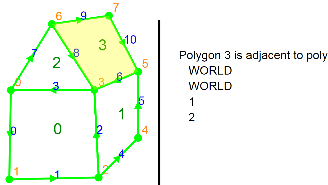
And finally, on selecting a polygon you're told which other polygons are its edge-sharing neighbors (not considering vertex sharing neighbors here but it's not hard to implement if necessary). I have recently updated the app to show each adjacent polygon only once.
A note on topology building
This app uses the direction of the edge as digitized (shown by the green arrow) to define left and right relationships. For a given edge, _left and _right record the polygons on either side of the edge. WORLD is constant that defines the undigitized area of the map. Once you've defined left and right for edges, and you have recorded how the edges and nodes connect, you have the basics of a vector GIS.
Be creative and find bugs! The user interface is ok in many respects but you can probably do things I didn't expect. For one, try creating a couple of polygons that share edges. Then click on a node on an external edge (one bounding WORLD) and keep clicking until you return to the same node. My app happily creates a new polygon that contains all the other existing polygons. This is a bug--not a feature!! (again, wait for version 2...). Similarly, if you enclose a polygon (or all polygons) entirely within another polygon, an error should be generated but is not. In future versions, this action will implicitly create a polygon with a hole in the middle, filled by the enclosed set of polygons.
Other Features
If you make some strangely shaped polygons suitable for gerrymandering, the polygon centroid may not be a good location for placing its label. since the centroid location may appear outside the polygon itself. To prevent this, I first split the polygon into triangles (a triangular decomposition or tessellation). Once done, I place the polygon label at the center of the triangle, whose centroid is closest to the polygon's centroid. This ensures that the label point always falls within the polygon. You can check the Show Tessellations box to see what this looks like when the polygon is closed (the tessellation disappears on the next selection or digitizing event).
Here's an example of a tessellated polygon: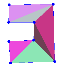
I really want to implement a digitizing feature that would eliminate the need to trace all of an existing polygon boundary when digitizing a neighboring polygon. I'm looking at using a network search algorithm (the same type of algorithm used for navigation in a mapping app) to trace the shortest path between 2 nodes along external edges so the user doesn't have to. Interesting problem!
Polygon Topology Builder, copyright James Mower 2019